
Masterarbeit
Entwicklung eines bruchmechanischen Finite-Elemente-Modells zur Rissausbreitung im Silizium am Beispiel des Thermischen Laserstrahl-Separierens (TLS)(Master Thesis) |
||
 |
|
|
1 Extended Abstract
Silicon wafers (short: wafer) are used as outlet substrate for the production of crystalline solar cells and modules in the photovoltaic industry. In order to increase the solar module yield, the solar cells are divided after the processing whereby the electric current halves itself and the serial resistance quarters. The Thermal Laser Separation (TLS) represents a damage poor separation process where mechanical stresses cause crack propagation in assistance of a combination of laser heating and cooling. The aim of this work is it to develop a fracture mechanics finite element model which can be used for simulates crack propagation during the TLS process. In detail, the following aspects should be figured out:
- Literature search for crack propagation in brittle materials, in particular regarding the difference between stable and unstable crack propagation as well as dynamic aspects in the crack propagation
- Development of a finite element model to simulate crack propagation in wafers during the TLS process with respect to quasi-static and/or dynamic behaviour
- Summary and discussion of the results as master thesis
In this chapter the motivation for the usage of Thermal Laser Separation (TLS) is described on the basis of the value of the photovoltaics in the Federal Republic of Germany. Using this motivation open questions to the TLS process are specified and the objectives of this thesis are drawn.
In the year 2014 approx. 6.9 % of the electricity consumption in the Federal Republic of Germany could be covered by German photovoltaic. On sunny days even 35 % to 50 % of the totally required power consumption were covered by photovoltaics. Up to the year 2050 the part of electricity from renewable energy sources is to be increased up to 65 % in Germany. [31]
One way to increase power from photovoltaics concepts is based on the improvement of solar modules efficiency. To increase the efficiency solar cells are divided after the processing. If a solar cell is halved, also the electric current is halved and the resistance is quartered. It can be shown that the yield in a solar module with 144 so called half cells can be increased by 5 % in comparison to a conventional solar module. [28]
For the production of these half cells silicon modules wafers must be separated in the processing. Therefore conventional techniques like mechanical scribing, laser scribing and laser cutting exist:
- mechanical scribing Mechanical scribing is subject to two operations, which are executed in a row. In the first step the surface of the cell is predamaged in form of a so called initial crack. For the initial crack material is removed on the top surface by means of a diamond sharpens -- this procedure is called scribing. Afterwards the cell is break by a defined load along the initial crack.
- laser scribing For laser scribing the initial crack is induced by a laser. Afterwards the cell is broken by a defined load along the initial crack similarly to second step of mechanical scribing.
- laser cutting During laser cutting the wafer absorbs laser radiation, which results to a defined heat entry along the desired cutting edge. The heat entry melts the material and finally leads to the separation of the cell. During the cutting process the laser is led relative to the cell, so that a defined cutting edge can be created.
Both mechanical scribing and laser cutting exhibit deviations in the surface quality along the cutting edges. Cutting edges, created by mechanical scribing, are frequently characterised by micro splinterings and micro cracks. Cells, which were separated by laser cutting, exhibit melting zones along the dividing line [32]. An alternative to the documented conventional separation processes of cells forms the so called Thermal Laser Separation (TLS). It serves for the thermal separation of thin-layered components by a laser beam inducing internal stresses. The main arguments for the application of the separation process lie in the facts that
- cutting edges can be fabricated with a high surface quality,
- no disposing of material is necessary,
- there arise improved mechanical and electrical characteristics of the cutting edge,
- brittle materials such as glass, silicon can be cut and
- components with high cutting speed (until 500 m/s) can be fabricated [5,7].
For practical workpiece separation by the TLS process, all necessary components are integrated in a machine tool. Such a machine tool consists of the three main parts:
- tool table (horizontal displaceable),
- workpiece holder (vaccum chuck1.1) and
- laser-cooler-configuartion,
as shown in figure 1.1. For separation of a component the workpiece is fixed in the holder. By the workpiece holder the component is horizontal led through the laser-cooler-configuration. In the principle sketch of figure 1.2 the laser-cooler-conguration is shown creating an initial crack on the top surface of the material. Finally this initial crack leads to the separation of the workpiece material by means of induced internal stresses.
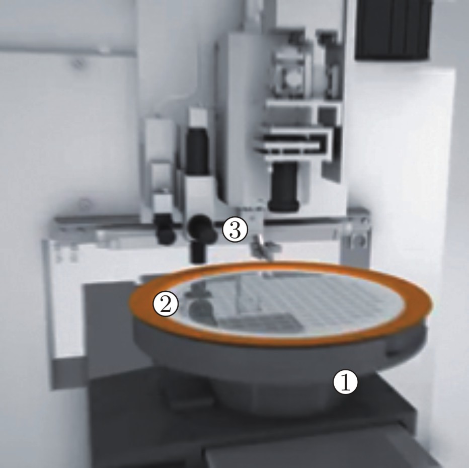
Fig 1.1: TLS machine tool with 1-tool table, 2-workpiece holder, 3-laser-cooler-configuration [1]
|
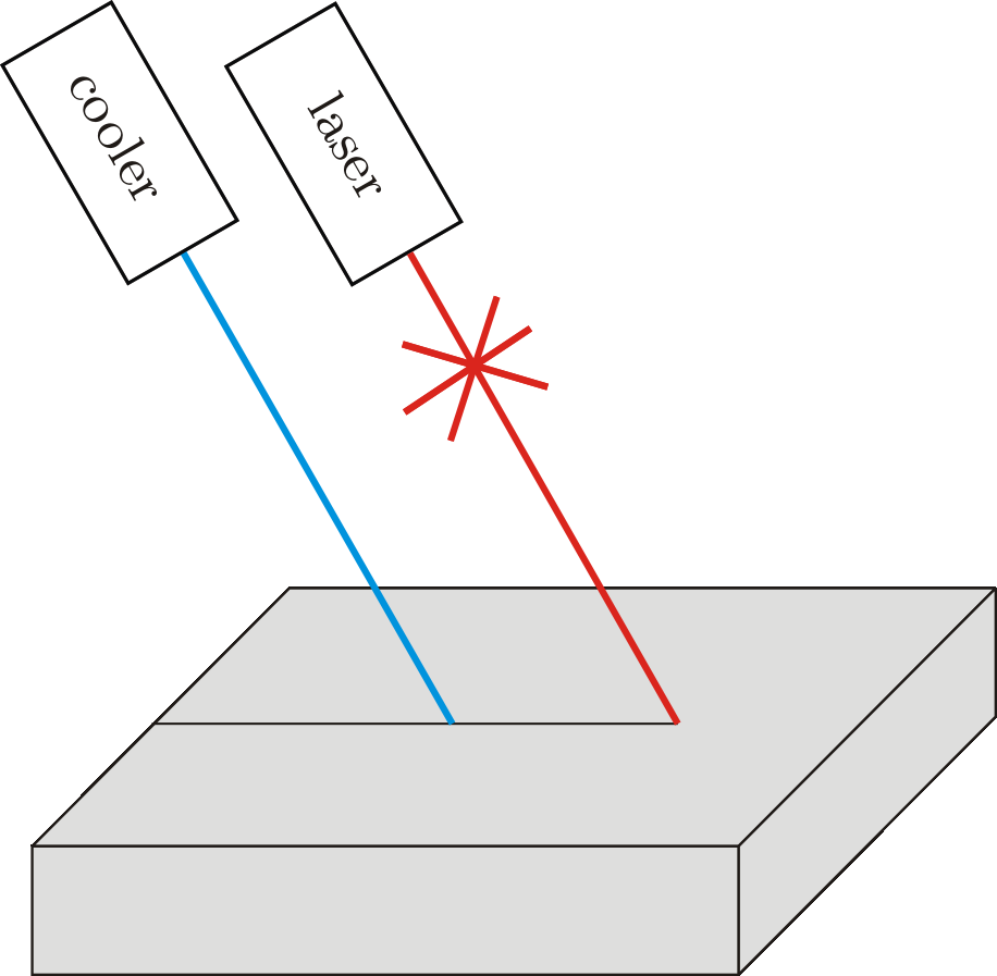
Fig 1.2: Principle sketch of the laser-cooler-configuration during TLS process
|
The separation of the material accompanies with a crack growth, which forms the cutting edge at the end of the process. The TLS process contains both process steps of mechanical scribing (impact of the laser beam) and the cutting, which in this case is done by self-equilibrating stresses.
The aim of this thesis is to analyse the mechanical processes during the crack propagation and to develop a general fracture mechanics crack propagation model. This model should take the following aspects of crack growth into account:
- static vs. dynamic Crack propagation models after [4] regards the crack propagation as quasi-static process. It is assumed that the crack propagates in the material very slowly. The more general crack propagation model should consider crack growth at high speed. This makes it necessary to include dynamic aspects of the crack growth.
- crack criterion For crack growth, a fracture mechanics criterion must be established. This criterion should be valid for static as well as dynamic crack growth.
- stability A crack can propagate in a stable or unstable manner. The general crack propagation model is to be able to illustrate both crack growth states.
- applicability The dynamic crack propagation model should be easily integrated into the TLS simulation.
The TLS process separates silicon wafers in assistance of a laser-cooler-configuration, which is passed along the surface of the workpiece. An initial crack induced by internal stresses is driven through the material caused by a high temperature gradient from laser-cooler-interaction -- the workpiece breaks along a defined edge. The description of the separation in form of a simulation and the derivation of two crack propagation models form the quintessential point of this documentation. The crack propagation models were compared with crack growth models from the literature. All three models are based on the evaluation of the energy release rate along a crack front. The energy release rates became calculated by the FE-Software ANSYS and informs how much energy at the crack front is available. In assistance of an iteration calculation the energy release rates are converted into crack growth increments until the rates reaches a critical value. Three models for this crack propagation simulation were presented:
- Crack propagation model 1,
 , can be found in the literature, normalizes the energy release rate along the crack front on a maximum crack propagation increment
  . The largest crack propagation increment occurs at that crack front point with the biggest energy release rate value. The crack propagation is understood as a static process with low crack propagation speed.
 - Crack propagation model 2,
 , is based on the model. In this model the crack propagation is defined by the energy surplus at the crack front. That means the difference between the energy at the crack front and a material specific minimum energy value provides crack propagation. The critical characteristic value is not constant and need to be calculated speed-dependently reflecting dynamic behaviour of crack growth. Speed dependence illustrates thereby dynamic aspects of crack growth.
 - Crack propagation model 3,
 , proceeds a uniform movement from crack front to crack front. The distance between these fronts is covered during a constant time increment at a defined speed, which is calculated by the energy release rates. This distance corresponds to the searched crack growth increment. Similarly to crack propagation model 2 dynamic and static aspects of crack growth are considered by speed dependence.
The application of the crack propagation models to a basic simulation model with the dimension ![]() ,
, ![]() ,
, ![]() with a displacement controlled load
with a displacement controlled load ![]() resp.
resp. ![]() shows that
shows that ![]() model supplies the largest crack propagation. The numerical experiment calculates fractured surfaces in the amount of
model supplies the largest crack propagation. The numerical experiment calculates fractured surfaces in the amount of ![]() . The
. The ![]() and
and ![]() model simulated 11 % smaller fractured surfaces with the same boundary conditions. This deviation is based on the consideration of the material specific value, which must be reached first for a crack propagation. Starting the simulation with different initial crack shapes -- in this thesis the straight and half Penny-shaped initial crack -- the resulting crack fronts deviate only slightly within a model. It could be shown that the resultant fractured surfaces of a crack propagation simulation with straight or half Penny-shaped initial crack only differentiate in an amount of 2.3 %.
model simulated 11 % smaller fractured surfaces with the same boundary conditions. This deviation is based on the consideration of the material specific value, which must be reached first for a crack propagation. Starting the simulation with different initial crack shapes -- in this thesis the straight and half Penny-shaped initial crack -- the resulting crack fronts deviate only slightly within a model. It could be shown that the resultant fractured surfaces of a crack propagation simulation with straight or half Penny-shaped initial crack only differentiate in an amount of 2.3 %.
The ![]() model has a unique feature: The consideration of time-independent and time-depended loads. In this thesis the simulation model was configured with linear increased resp. decreased displacement controlled loads and consequences were analysed for crack propagation. It could be shown that only the
model has a unique feature: The consideration of time-independent and time-depended loads. In this thesis the simulation model was configured with linear increased resp. decreased displacement controlled loads and consequences were analysed for crack propagation. It could be shown that only the ![]() model reflects whether a load is initiated fast (high extension rate) or slowly (low extension rate). Thus an extension rate of
model reflects whether a load is initiated fast (high extension rate) or slowly (low extension rate). Thus an extension rate of ![]() results in a
results in a ![]() smaller fractured surface in relation to the static equivalent. For validation the
smaller fractured surface in relation to the static equivalent. For validation the ![]() model sufficiently small extension rates could be constituted, which effected fractured surface values in the amount of the static equivalent. This means in summary that the
model sufficiently small extension rates could be constituted, which effected fractured surface values in the amount of the static equivalent. This means in summary that the ![]() model supplies for low crack speeds static crack propagation values. How far a crack propagates, depends on the extension rate of the displacement-controlled load. Thus, questions of quantitative evaluation of cracks, which propagate at high speed and are subject to time-dependent loads, can be answered for the first time by the
model supplies for low crack speeds static crack propagation values. How far a crack propagates, depends on the extension rate of the displacement-controlled load. Thus, questions of quantitative evaluation of cracks, which propagate at high speed and are subject to time-dependent loads, can be answered for the first time by the ![]() model.
model.